 Technical information
[Notes]
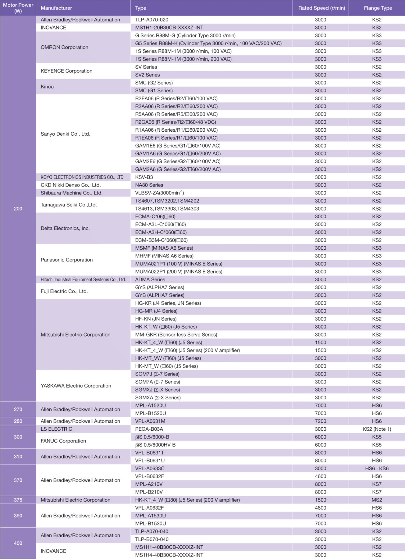
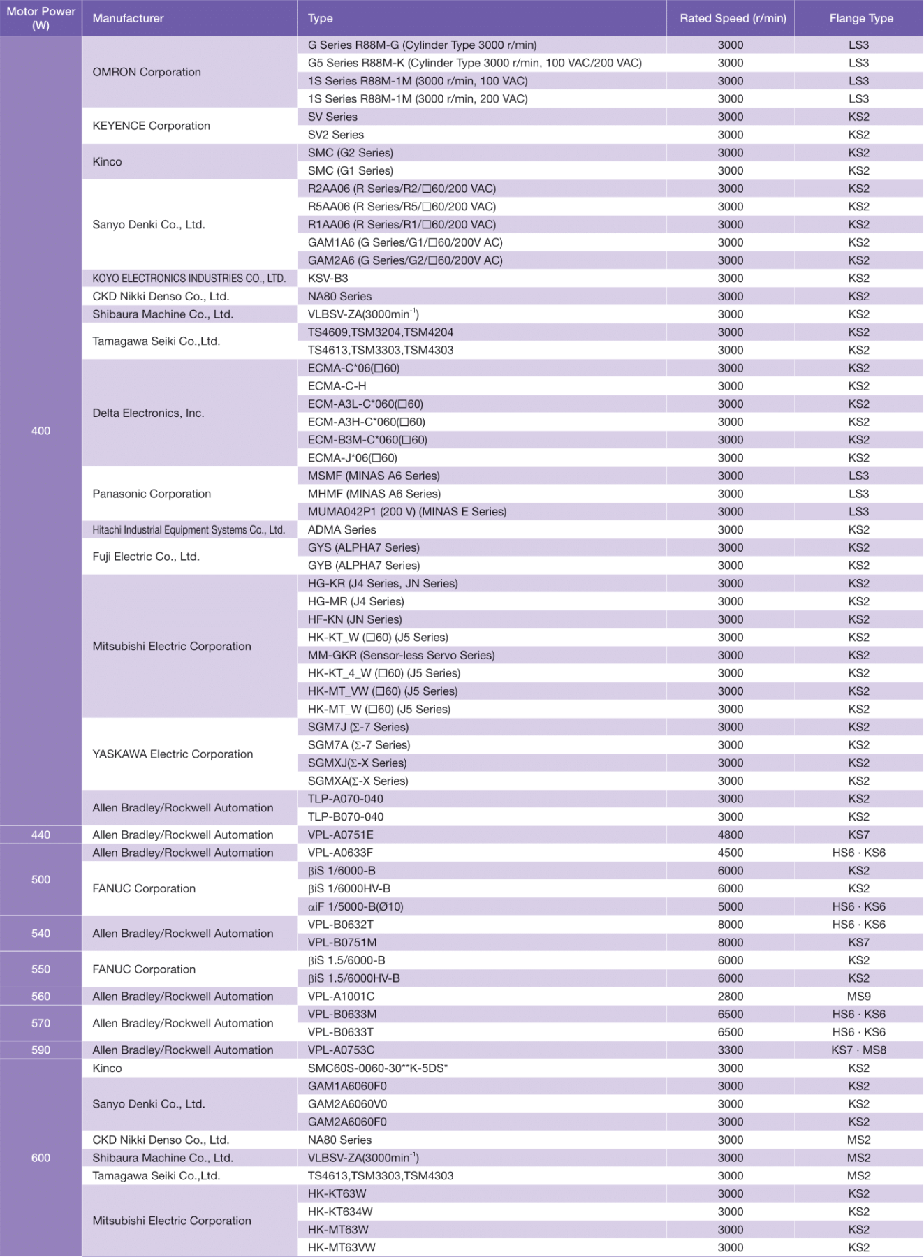
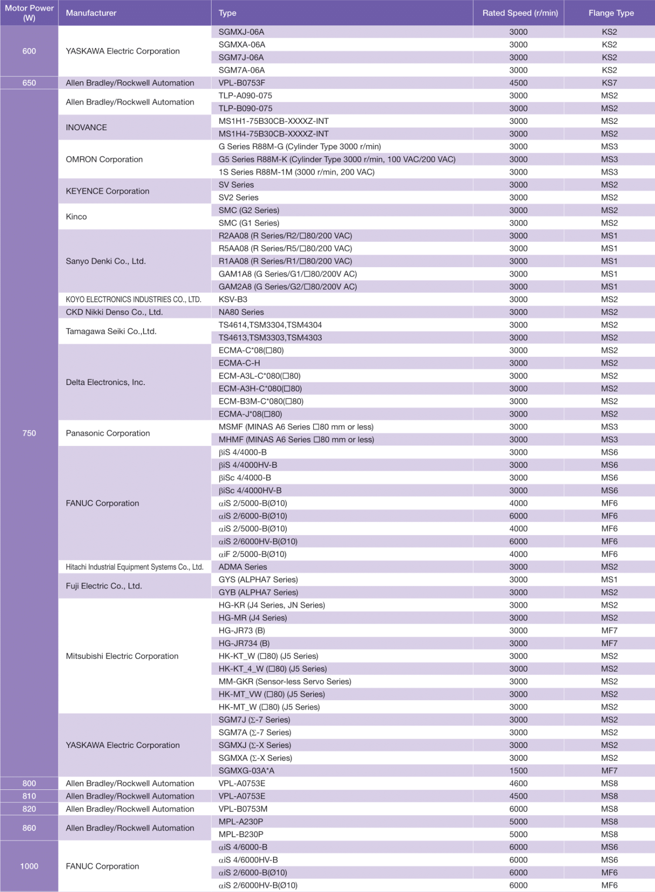
● The tables show below representative examples as of October 2025. The specifications of servo motors are subject to change. When placing an order, be sure to check the dimensions of the servo motor flange you are going to use and the dimensions of the area in which our reducer for servo motor will be installed.
● The tables below show servo motors of various standard specifications.For servo motors using an oil seal or other options, be sure to check whether a reducer can be mounted by referencing the Detailed Dimensions of Input Shaft and Flange Shapes.
● For more details, please contact your nearest Sales Office or the CS Center.
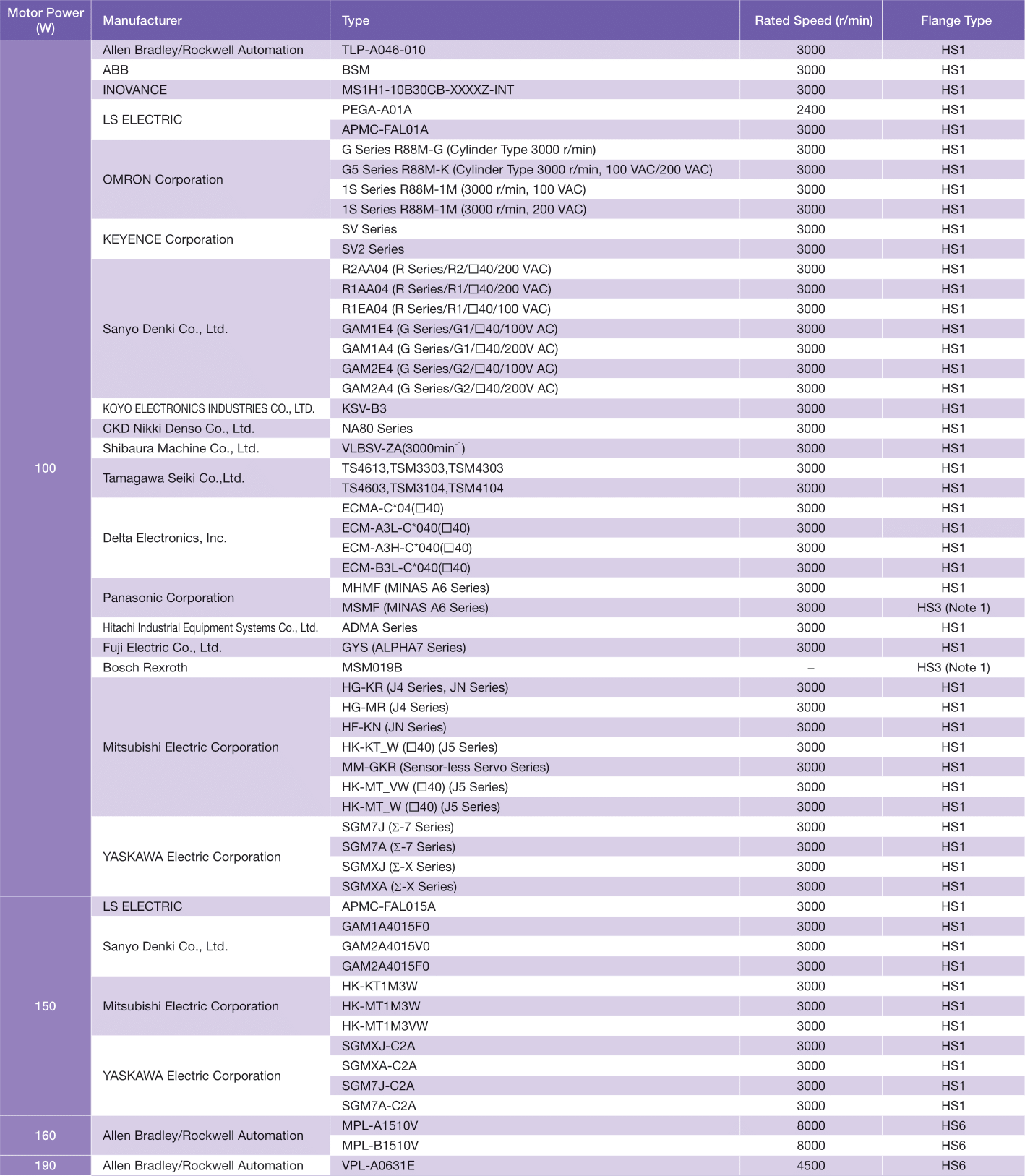
Note 1. Please notice that the dimensions of the square flange of the servo motor and the dimensions of the reducer servo motor mounting square flange are different. Please be cautious.
Selection Process
The high stiffness reducer can be selected as follows.Downloadthe catalog for details.
- 1 Calculation of average load torque on output shaft side in terms of usage
- 2-1 Calculation of average output RPM
- 2-2 Deciding on reduction ratio
- 2-3 Calculation of average input RPM
- 2-4 Calculation of maximum input RPM
- 3 Confirm that with performance table values that satisfy the usage conditions
- 4 Select the motor and select a motor mounting flange type that can be mounted in accordance.
- 5 Calculation of reducer Life time
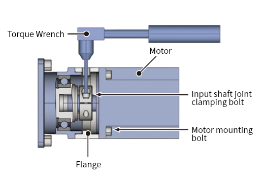
Motor Mounting
- Turn the input shaft joint, then align the bolt head of the input shaft joint clamping to the wrench hole of the input shaft joint clamping on top of the flange.
- Wipe off the input shaft joint guide and motor output shaft of the servo motor with a rust-preventive agent, oil, etc.
-
Insert the motor into the reducer body.
*When a bush is provided, align the position of the slit of the bush with the slit of the input shaft joint as shown in Figure 1.
Also, if the motor shaft has a key groove, align the position of the slit of the bush with the key groove as shown in Figure 2. - Secure the motor and reducer flange with the motor mounting bolts at the tightening torques shown in the table below.
- Secure the input shaft joint clamping bolts at the tightening torques shown in the table below. *Do not tighten the clamping bolt without inserting the shaft applicable to the flange type into the input shaft joint.
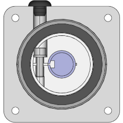
- Mount the rubber cap (accessory) to the wrench hole for input shaft joint clamping.
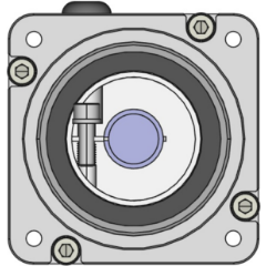
Figure 1 Without Key Groove
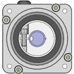
Figure 2 With Key Groove
| Bolt Size | Tightening Torque (N・m) |
| M3 | 1.6 |
| M4 | 4.4 |
| M5 | 8.3 |
| M6 | 14.2 |
[Reference]
The bolt strength type (JIS B 1051) should be 12.9.
Input Shaft Joint Clamping Bolt Tightening Torques (Reference Values)
| Bolt Size | Tightening Torque (N・m) |
| M4 | 5.4 |
| M5 | 10.8 |
Installation Method
- ● Secure with bolts on a vibration-free and flat machine-processed surface.
- ● Tighten the bolts with the tightening torque shown in the table below.
- ● If the foundation is bad or the mounting surface is not flat enough, vibration may occur during operation and the service life of the reducer may be shortened.
- ● Make sure the flatness of the mounting surface is 0.1 mm or less.
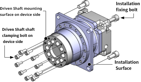
| Bolt Size | Tightening Torque (N・m) | |
| Driven Shaft shaft clamping bolt on device side | Installation fixing bolt | |
| M4 | 5.4 | - |
| M5 | 10.8 | 8.3 |
| M6 | - | 14.2 |
| M8 | - | 29.4 |
[Reference]
The bolt strength type (JIS B 1051) should be 12.9.
Recommended Bolts: Hex Head Cap Screws(JIS B 1176)