High Stiffness Reducer DGF type
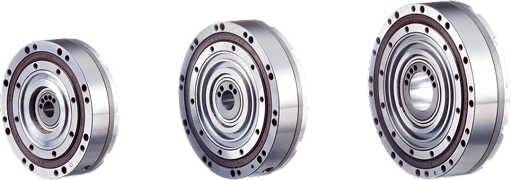
3Frame Sizes
OD: 71.5mm /81.5mm /91.5mm
2stage Reduction
1/50・1/100
Features
Our reducer can contain input bearing inside even it is already very light and thin. Thus, users can feel how compact and light firmly when designing equipment.
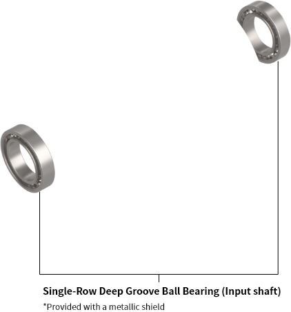
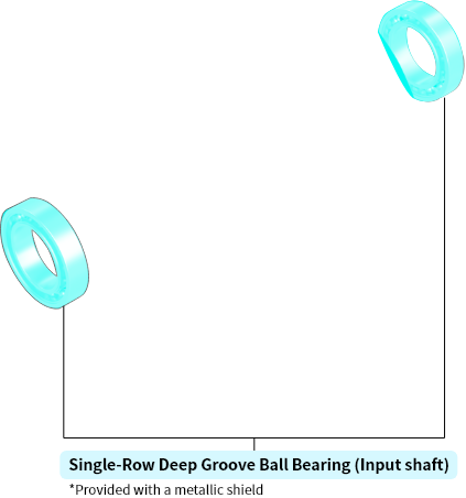
Flat and lightweight with input bearing inside
Making devices more compact


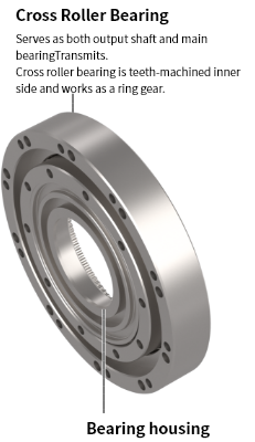
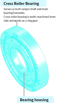
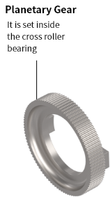
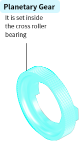
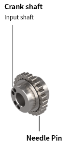
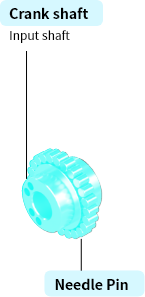
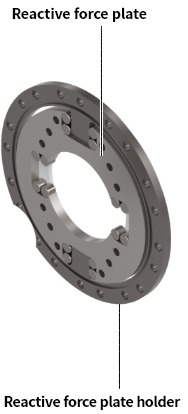
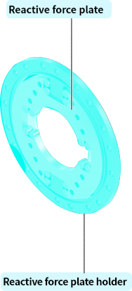
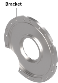
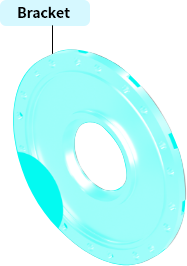
Structure
[Structure] Input bearing inside


Model
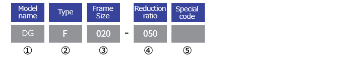
| ①Model name | DG Series |
|---|---|
| ②Type | F:Flat |
| ③Frame Size* | 005:5.4N·m |
| 020:16N·m | |
| 030:28N·m | |
| ④Reduction ratio | 050:1/50 |
| 100:1/100 | |
| ⑤Special code | For special specifications, additional identification symbols will be used. |
* Each Frame Size represents their corresponding Rated Torque
Selection Process
The high stiffness reducer can be selected as follows. Donwload the catalog for details.
1
Calculation of average load torque on output shaft side in terms of usage
2
-1
Calculation of average output RPM
2
-2
Deciding on reduction ratio
2
-3
Calculation of average input RPM
2
-4
Calculation of maximum input RPM
3
Confirmation of whether the usage conditions meet the Performance Table values
4
Calculation of reducer Life time
Contact us
Before use
Be sure to enter the items marked "*Required".
Check our personal information protection policy (privacy policy) before use.
Enter inquiry
Enter each item and click the "Confirm" button.
フォームが表示されるまでしばらくお待ち下さい。
恐れ入りますが、しばらくお待ちいただいてもフォームが表示されない場合は、こちらまでお問い合わせください。