High Stiffness Reducer Installation method
Gear Head type Installation Method
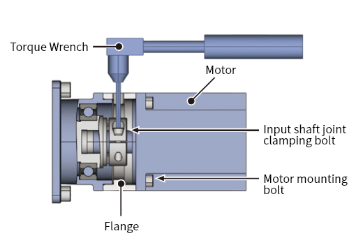
Motor Mounting
- Turn the input shaft joint, then align the bolt head of the input shaft joint clamping to the wrench hole of the input shaft joint clamping on top of the flange.
- Wipe off the input shaft joint guide and motor output shaft of the servo motor with a rust-preventive agent, oil, etc.
-
Insert the motor into the reducer body.
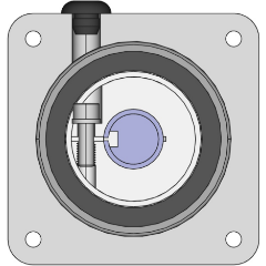
*When a bush is provided, align the position of the slit of the bush with the slit of the input shaft joint as shown in Figure 1.
Also, if the motor shaft has a key groove, align the position of the slit of the bush with the key groove as shown in Figure 2. - Secure the motor and reducer flange with the motor mounting bolts at the tightening torques shown in the table below.
- Secure the input shaft joint clamping bolts at the tightening torques shown in the table below. *Do not tighten the clamping bolt without inserting the shaft applicable to the flange type into the input shaft joint.
- Mount the rubber cap (accessory) to the wrench hole for input shaft joint clamping.
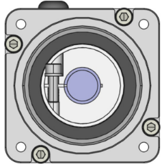
Figure 1 Without Key Groove
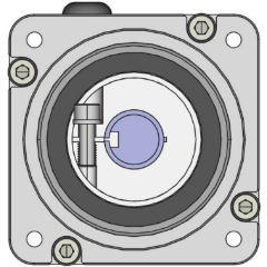
Figure 2 With Key Groove
| Bolt Size | Tightening Torque (N・m) |
|---|---|
| M3 | 1.6 |
| M4 | 4.4 |
| M5 | 8.3 |
| M6 | 14.2 |
[Reference]
The bolt strength type (JIS B 1051) should be 12.9.
Input Shaft Joint Clamping Bolt Tightening Torques (Reference Values)
| Bolt Size | Tightening Torque (N・m) |
|---|---|
| M4 | 5.4 |
| M5 | 10.8 |
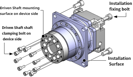
Installation Method
- ● Secure with bolts on a vibration-free and flat machine-processed surface.
- ● Tighten the bolts with the tightening torque shown in the table below.
- ● If the foundation is bad or the mounting surface is not flat enough, vibration may occur during operation and the service life of the reducer may be shortened.
- ● Make sure the flatness of the mounting surface is 0.1 mm or less.
| Bolt Size | Tightening Torque (N・m) | |
|---|---|---|
| Driven Shaft shaft clamping bolt on device side | Installation fixing bolt | |
| M4 | 5.4 | - |
| M5 | 10.8 | 8.3 |
| M6 | - | 14.2 |
| M8 | - | 29.4 |
[Reference]
The bolt strength type (JIS B 1051) should be 12.9.
Recommended Bolts: Hex Head Cap Screws(JIS B 1176)
DGH type Installation Method
- 1. Example to mount motor ▼
- 2. To mount reducer ▼
- 2. (1)To fix reducer ▼
- 2. (2)To fasten Input/output part ▼
- 3. Cautions when using a hollow structure ▼
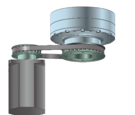
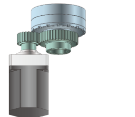
1. Example to mount motor
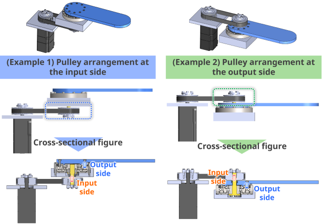
Timing Belt Connection
Gear Connection
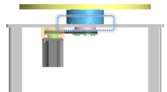
2. How to mount reducer (Example: Use on a table)
Mounting on input side
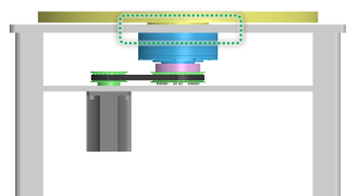
Mounting on output side
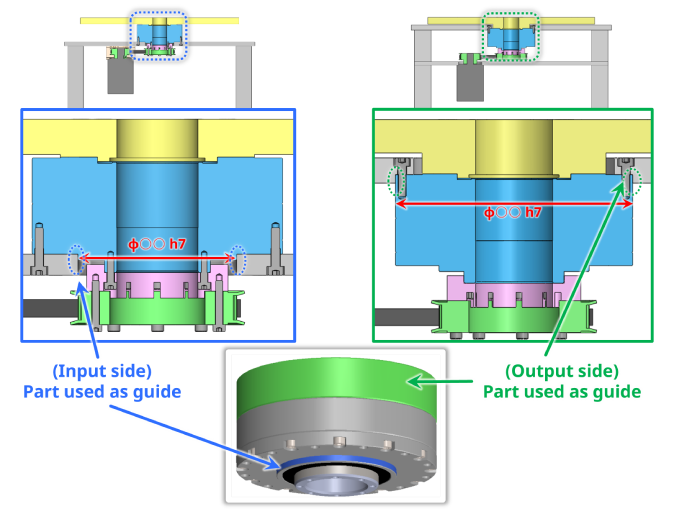
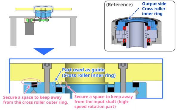
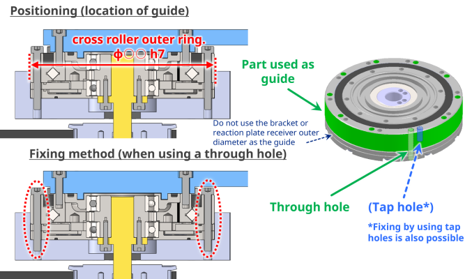
2. (1)To fix reducer (Positioning)
Mounting on input side
Mounting on output side
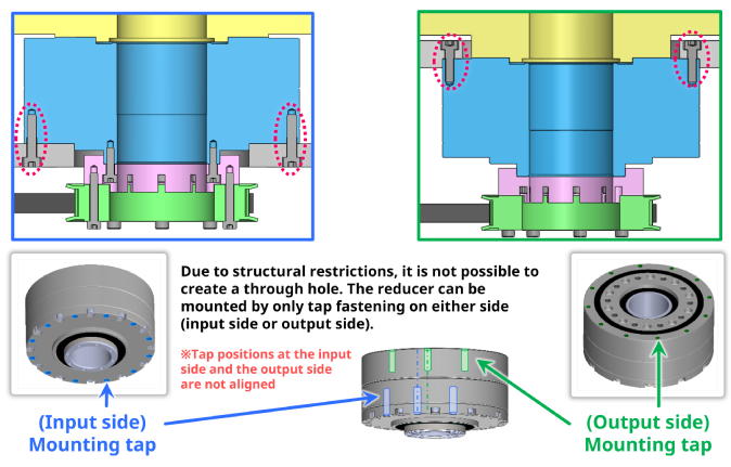
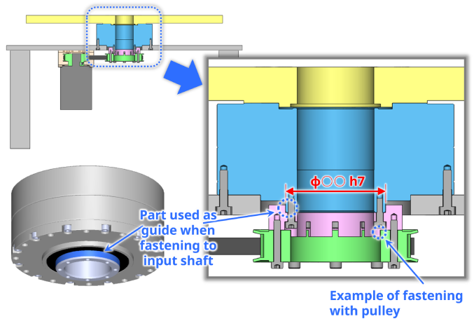
2. (2)To fix reducer (Installing)
Mounting on input side
Mounting on output side
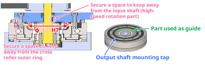
2. (2)To fasten Input/output part (Positioning output part)
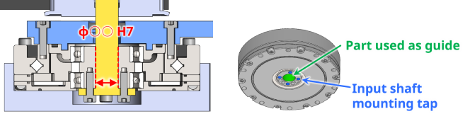
2. (2)To fasten Input/output part (Positioning input part)
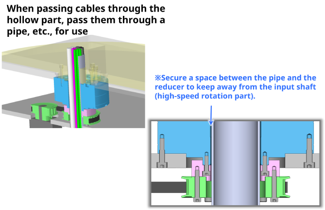
3. Cautions when using a hollow structure
DGF type Installation Method
- 1. To mount reducer▼
- 2. To fix reducer▼
- 3. To fasten output part▼
- 4. To fasten input part▼
- 5. Grease filling, etc.▼
1. How to mount reducer (Example)
2. To fix reducer (Positioning and fixing)
3. How to position/fix reducer
4. To fasten input part (Positioning))
5. Grease filling and sealing
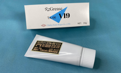
《Grease filling》
Fill 70 to 80 % of
the spatial volume of the device with our dedicated grease (sold
separately).
(Grease density : 0.9 g/?)
・The amount of grease required differs depending on the type of housing.
・Grease
is sealed in the reducer when it is shipped from our factory.
《Sealing》
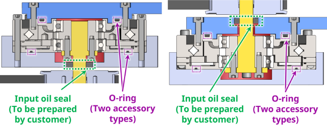
The flat and lightweight type (DGF) reducer does not have a sealed structure.
If necessary, please install a seal or other on the equipment side to prevent
grease leaks.
Also, please place the O-rings (two types) supplied with
the product where the reducer is mounted.